×
![]()
Test Area 1-115 Test Stand 1-3 Photos
Bldg. 8698, Test Stand 1-3. The existing structural base of Test Stand 1-3 is a reinforced, poured concrete structure stepped against the northern side of Leuhman Ridg. The overall measurements of the base, including the terminal roof deck, the valve room deck, and the working deck, are 59 feet wide by 75 feet long, with a maximum height of 92 feet (from the north footing of the working deck to the roof deck of the terminal room). The at-grade deck of the structure is rectangular in shape, measuring approximately 44 feet wide by 38 feet deep. A small rectangular opening on this deck provides access to rooms below grade that were control and terminal rooms. Steel posts around the edge are all that remain of the original railings. On the eastern and western sides of this section of the test stand base are U- shaped cells measuring approximately 25 by 11 feet and approximately 50 feet high. The walls of the terminal room structure are the base of the U and have two parallel steel anchor bolts running vertically from the base of the stand to the terminal roof deck. The 20-foot-wide- by 15-foot-long valve room deck is located in the southeastern comer of the terminal roof deck and has a small opening with a wall-mounted steel ladder leading to the valve room below. Immediately north of the terminal roof deck, and 15 feet lower, is the irregularly shaped working deck. This deck is 60 feet wide at the juncture with the terminal room structure, 36 feet wide at the center, and 45 feet wide at the northern edge. The overall length of the deck, from the terminal room to the northern edge, is 29 feet.The working deck is 42 feet above grade at the juncture with the terminal room and 75 feet above grade at the northern edge. This deck has six octagonal shaped openings to the structure below arranged in two rows of three. The test stands appear to be in fair condition, with standing water pooling in the rooms beneath the decks, spalling concrete in places, and general lack of maintenance. The superstructure of the building is entirely missing. It was removed during the late 1960s or early 1970s.
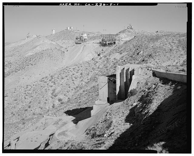
BUILDING 8698, TEST STAND 1-3, WEST ELEVATION. NOTE TUNNEL BETWEEN BLDG. 8668 AND TEST STAND 1-3. TEST AREA 1-120 IN THE MIDDLE DISTANCE, AND TEST AREA 1-125 ON THE HORIZON. Looking northeast from the roof of Building 8668, Instrumentation and Control Center. Note: Photograph CA-236-F-2 is an 8' x 10' enlargement from a 4' x 5' negative. This view is a photocopy of a recent resin coated print made from a print held at the Main Base History Office, Edwards Air Force Base, California.
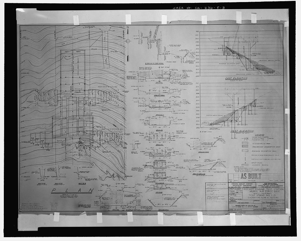
'TEST STAND NO. 1-3, EXCAVATION PLAN & SECTIONS.' Specifications No. ENG 04-353-50-10; Drawing No. 60-0906; no sheet number within title block; D.O. SERIES 1109/10. Stamped: AS BUILT. No revisions or revision dates. Last work date on this drawing 'Checked by EAG, 1/31/49.' Though this drawing is specific to Test Stand 1-3, it also illustrates the general methods used for excavation design and retaining wall construction at Test Stand 1-5.
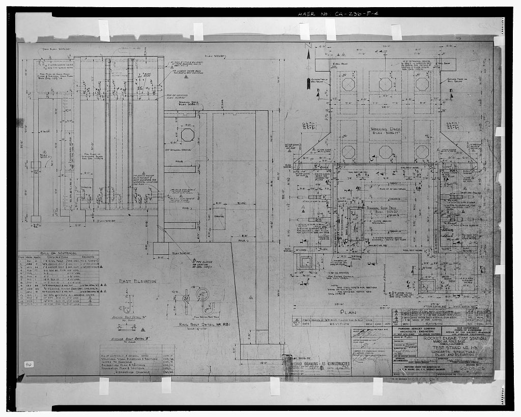
'TEST STAND NO. 1-3, CONCRETE STRUCTURAL PLAN AND ELEVATION.' Specifications No. OC11-50-10; Drawing No. 60-09-06; no sheet number within title block. D.O. SERIES 1109/12 REV. E. Stamped: RECORD DRAWING - AS CONSTRUCTED. Below stamp: Contract DA-04-353 Eng. 177, Rev. E; Date: 17 Dec. 1951.
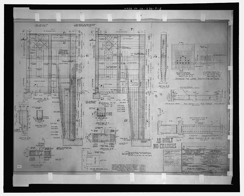
'TEST STAND 1-3, CONCRETE STRUCTURAL SECTIONS AND DETAILS.' Specifications No. OC12-50-10; Drawing No. 60-09-06; no sheet number within title block. D.O. SERIES 1109/17, Rev. A. Stamped: AS BUILT; NO CHANGES. Date of Revision A: 11/1/50.
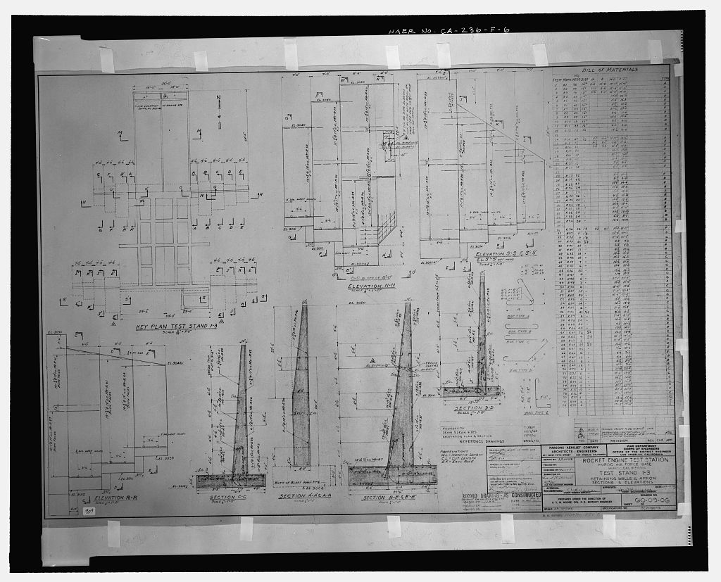
'TEST STAND NO. 1-3, RETAINING WALLS & APRON, SECTIONS & ELEVATIONS.' Specifications No. OC11-50-10; Drawing No. 60-09-06; no sheet number within title block. D.O. SERIES 1109/20, Rev. B. Stamped: RECORD DRAWING - AS CONSTRUCTED. Below stamp: Contract DA-04-353 Eng. 177, Rev. B; Date: 26 Dec. 1951.