Test Area 1-120 Description and Photos
In November 1954, final drawings and specifications were prepared for Test Stand 1-A by the Ralph M. Parsons Company. Drawings and specifications had to reflect the latest in design techniques, which made Test Stand 1-A the foremost of the new rocket test facilities. It was designed for 1,000,000-pound thrust capacity with a very large safety factor and was the first test stand on which a complete Atlas missile system could be tested (Eppley 1961).On March 31,1955, the construction contract for Test Stand 1 -A was awarded to G. A. Fuller Construction Company by the Corps. Groundbreaking was in May 1955, and construction of Test Stand 1-A was completed in November 1956.
The control room building (Bldg. 8783) was designed to protect test support personnel from mishaps on the rocket test stands. It served as a mission control room, office space, and rocket firing viewing area complete with window glass thick enough to withstand explosions on the test stands. A tunnel system linked the control room building with Test Stand 1 -A and later with Test Stands 2-A and 1-B. The mission control room originally contained strip charts, oscillographs, and high-frequency FM tape-recording systems, which allowed the engineers to analyze the test data. The room had more than 500 data-collecting channels with 300 recorders. The actual rocket firing was controlled by mechanical clock timers and sequencers.
In addition to the control room, personnel could view firings on the test stand from one of the observation and camera buildings positioned around the test stand. These bunkers were positioned around the sides and front of the test stand and often were built into the mesa for added protection. The form of the bunkers was consistently a poured concrete box with an entry door at the rear and narrow, horizontal viewing windows on the front that were shaded with a metal awning.
The Convair Division of the General Dynamics Corporation had practically completed tests on the Atlas missile at Test Stand 1-A when the missile malfunctioned and exploded during a test on March 27,1959. The test stand was damaged to such an extent that is was impractical to rebuild it for the two tests remaining to complete the Atlas program. Test Stand 1-A was transferred to Rocketdyne under a use agreement signed on July 28, 1959, by Air Force and Rocketdyne representatives. Under the use agreement, Rocketdyne would modify Test Stand 1-A at a cost of $3 million to test the F-1 engine. This figure would include not only the modification work, but upgrading of the test equipment. Modified Test Stand 1-A was the cornerstone of what was to become the NASA Static Rocket Engine Test Complex, which would eventually include Test Stand 1-B, Test Stand 2-A, and the control room. The control room for Test Stand 1-A also was modified.
A target date of September 1960 was set for completing modifications to Test Stand 1-A. At that time, the test stand would be fully operational. The test stand reconfiguration activity in 1959 through 1960 consisted of the following modifications:
- The Atlas tower was removed.
- A new thrust structure with a load measurement system was installed.
- The run tank support structure was fabricated.
- Propellant ready storage and run tanks and an engine feed system for LOj and RP-1 were installed.
- The flame deflector system was enlarged and the test stand fire control system expanded.
- New instrumentation and control systems were added and the data acquisition system expanded.
The test stand was converted from the Atlas missile configuration to the present configuration for static testing of the E-1 and F-1 engines. Modifications were made to upgrade the test stand to a 1,600,000-pound thrust capability. Development of the E-1 and F-1 engines reflected a shift in priorities for the test area from Cold War ICBMs to manned space flight. Approximately 700 engine firings were accomplished from activation in 1960 until research and development were completed in 1969.
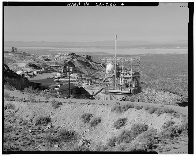
TEST AREA 1-120 OVERVIEW, TEST AREA 1-115 IN MIDDLE DISTANCE, AND TEST AREA 1-110 IN FAR DISTANCE AT EXTREME LEFT. ROGERS DRY LAKE AND THE HANGARS AT MAIN BASE ARE VISIBLE IN THE FAR RIGHT DISTANCE. TEST STANDS 2-A AND 1-A ARE NEAREST THE CAMERA. Looking west southwest..
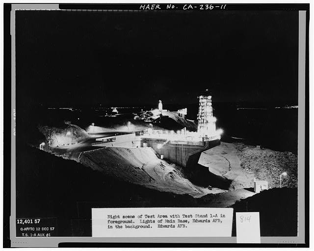
'NIGHT SCENE OF TEST AREA WITH TEST STAND 1-A IN FOREGROUND. LIGHTS OF MAIN BASE, EDWARDS AFB, IN THE BACKGROUND. EDWARDS AFB.' Test Area 1-120. Looking west past Test Stand 1-A to Test Area 1-115 and Test Area 1-110.
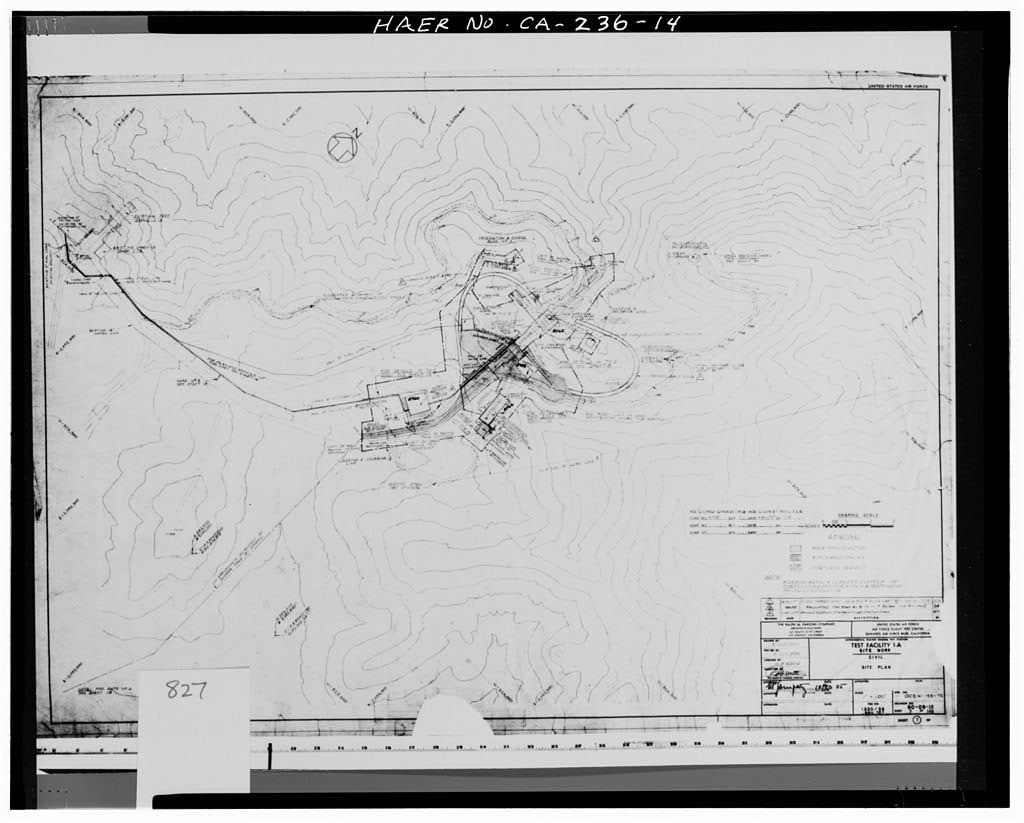
'SITE WORK, CIVIL, SITE PLAN.' Test Area 1-120. Specifications No. OC2-55-72; Drawing No. 60-09-12; sheet 7 of 148; file no. 1320/58, Rev. C. Stamped: RECORD DRAWING - AS CONSTRUCTED. Below stamp: Contract no. 4338 Rev. C, Date: 16 April 1957.
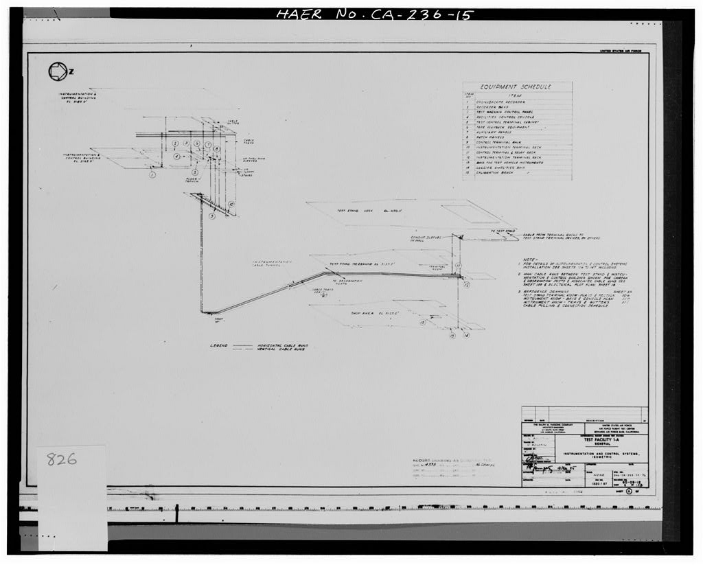
'GENERAL, INSTRUMENTATION AND CONTROL SYSTEMS, ISOMETRIC.' Test Area 1-120.